Maximizing the performance of your boat is not just getting the right motor for your boat; many parameters play a big role in its performance. Top-end, hole-shot or cruising speeds, your rig needs to be set right.
What Exactly is Torque?
Torque is the twisting or rotating effort of any shaft, such as the drive shaft driven by an outboard engine. Torque is commonly expressed in pound-feet. Torque is directly proportional to the horsepower passing through and inversely proportional to the shaft speed (RPM).
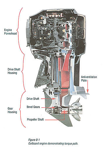
In Figure 8-1, the engine delivers torque through its crankshaft to the drive shaft and finally to the propeller shaft. The transfer of torque, or twisting force, from the drive shaft to the propeller shaft is made through gears. The torque developed at the engine is thus delivered through shafts and gears to the propeller. However, there usually is a 5% to 10% loss of horsepower, and thus torque, by the time it reaches the propeller, due to the friction between moving parts.
What Does Motor Gearing Have to Do with Torque?
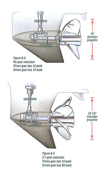
When there is no gear reduction, as in Figure 8-3, 5000 engine RPM turns the propeller at 5000 RPM. Here, there is no change in torque. The propeller sees the same torque that is coming from the powerhead, but for frictional losses.
If gear reduction is used, however, as in Figure 8-4 where a two-to-one (2:1) gear reduction exists, the 5000 engine RPM is reduced to 2500 RPM at the propeller. Therefore, by cutting propeller shaft speed in half, the torque has been doubled.
As the higher torque is transmitted to the propeller shaft with gear reduction, a larger-diameter, higher-pitch propeller (Figure 8-4) is required. A slower-turning, larger-diameter, higher-pitch propeller is more efficient than a faster-turning, smaller-diameter, lower-pitch propeller. This usually means better acceleration as well as better top speed, up to the point where the higher drag of the larger, higher-reduction gearcase overtakes the propeller efficiency benefit. That is why at higher racing speeds a smaller, lower-drag gearcase with little if any gear reduction will run faster than a larger gearcase with much gear reduction, despite the greater propeller efficiency associated with the larger gearcase. Gearcase drag is proportional to the velocity squared.
The pitch acts like another set of gears with a given boat and load. When using a propeller from a propeller line designed for your engine, correct pitch is evident when, at wide-open-throttle, the engine runs within the manufacturer's specified RPM range.
The faster the boat moves, given a specific engine and gear ratio, the smaller the ideal propeller diameter will be. The propeller diameter goes down as the pitch goes up (fully submerged propellers only).
How Does Propeller Torque Produce Boat Roll?
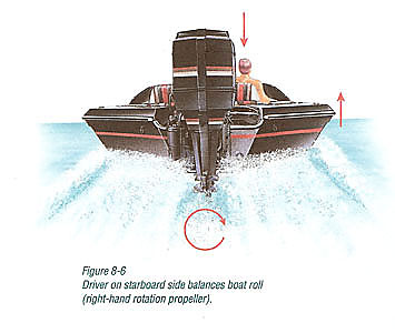
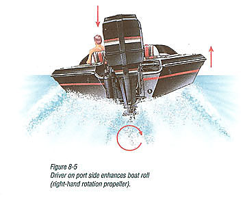
When observing from behind a boat, the propeller turns clockwise when underway with a normal right-hand propeller. As water resists the clockwise rotating propeller, it causes the boat to roll slightly in the opposite direction (counterclockwise) or down on the left (port) side and up on the right (starboard) side (Figure 8-5). To offset this slight imbalance, the driver's seat is placed on the starboard side (Figure 8-6). Boats differ significantly in the degree of their reaction to prop torque.
What is the Correct Height to Mount the Engine on the Transom?
For a propeller to best satisfy particular boating needs, the engine must be attached to the transom at the correct height.
Over the past 30 years, industry standards for transom height have been developed:
- 15" for "short shaft" engines;
- 20" for "long shaft" engines; and
- 25" for "extra-long shaft" engines.
Standard Mounting
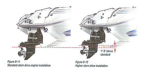
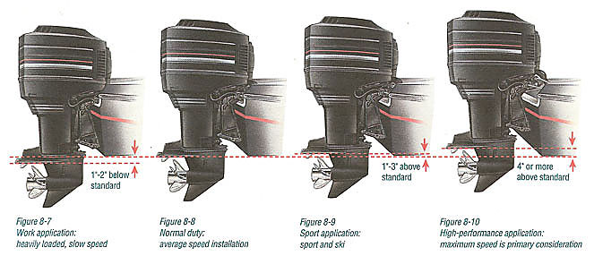
A correct conventional installation would generally place the antiventilation plate on many engines about even with the boat bottom when the engine propeller shaft is parallel to the boat bottom (Figures 8-8 and 8-11).
Lower Mounting
Setting the engine lower (deeper in the water) (Figure 8-7) tends to:
- Cause excessive spray.
- Increase gearcase drag.
- Reduce underwater clearance.
- Adversely affect handling of faster boats.
However, there are exceptions to the above. Many small fishing engines and some larger engines are designed to run with their anti-ventilation plate an inch or two below the boat bottom. This can assist in reducing or eliminating propeller ventilation.
Higher Mounting
In the past, the only negative effect from mounting an outboard or stern drive higher than standard was an increase in propeller ventilation, which could cause difficulty in planing, particularly with heavier loads.
However, as available power has steadily increased, and with improvements in propeller design-particularly in the field of high-performance propellers, owners of faster boats have explored a new, higher range of performance that can be achieved by raising their engines above the old standard height. It is becoming more common to raise outboards three inches or more above the standard on fast-boat installations (Figures 8-9 and 8-10). Outboard manufacturers are now recommending that engines be mounted higher than the old standard, provided boat speed justifies it. In fact, a growing number of boat builders are building their faster outboard-powered boats with transoms 1" to 3" above the standard height (usually 20").
Boat builders of sport boats using stern drive propulsion are only slightly more conservative. Referring to the use of non-racing stern drives, the "X" dimension is raised on fast, conventional single-drive boats by 1" to 2" (Figure 8-12) and on other bottom styles (such as catamarans) by 2" to 3". Twin drive installations will call for even less elevation.
However, by raising an engine or drive to excessive transom heights, the increased risk of engine overheating due to insufficient cooling water is a major concern. Manufacturers cannot be held responsible for, nor accept, any warranty obligations for overheating damage caused from this type of excessive setup and operation. Thus, the driver must accept the responsibility of constantly monitoring the engine cooling water pressure and/or temperature.
Some engines are equipped with overheat horns, but any engine can be rigged with a water pressure gauge. However, a water pressure gauge can give you a false sense of security from a temporary, high pressure reading, resulting from a steam pocket trapped at the top of the block. And the overheat horn doesn’t give any feel for how close to overheating the engine is running. A water temperature gauge is the most reliable instrument for monitoring the operating temperature of your engine.
Top-of-the-block water temperature should not be allowed to exceed 140° (60°C) while water pressure at full throttle should not be allowed to fall below 70% of the full throttle reading taken at a more conventional transom height.
Remember, as engine installation height is increased, your freedom to trim the engine out without overheating is reduced.
Raising the engine can provide several advantages:
- Reduced lower unit drag, thus increased speed (approximately one MPH per inch in the 60-80 MPH range).
- Improved handling on faster boats. Excessive rudder in the water at higher speeds on a light boat can increase handling problems and cause "chine walking" (left to right to left rocking motion).
- Greater clearance to underwater obstacles.
- When combined with trimming out (the usual case), reduction of steering torque to nothing, especially at around a 23" transom height for a long-shaft engine.
 In a few cases, improved planing off, by allowing the propeller to take in surface air, thus considerably increasing engine RPM, which results in more available horsepower when it is needed.
There are also some disadvantages to raising the engine above standard height (Figure 8-13):
- As the engine is raised higher on the transom, the risk of overheating from lack of sufficient cooling water increases. Cooling water flow must be monitored more frequently.
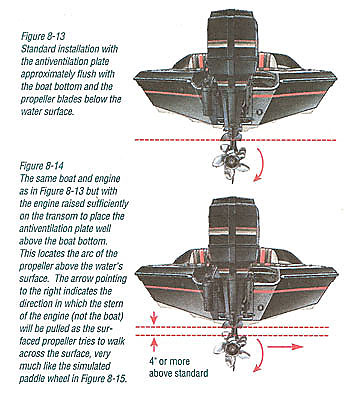
- At higher transom heights the trim tab is no longer effective as a means of altering steering torque. Heavy steering torque may be encountered, and the driver must maintain a continuous firm grip on the wheel at all times when neither power steering nor no-feedback steering is employed (Figure 8-14).
- Engine raising is not for heavier, slower boats.
- A higher-rake, cupped, sharp-edged propeller is generally required.
- In many cases planing off, particularly with a load, is more difficult.
- There is a little more vibration, which may reduce riding comfort, and eventually may loosen parts on the engine and boat.
 Dual-engine installations provide a new problem because, during turns, the outside engine is lifted higher out of the water than a single, centrally located engine. This usually means that with dual engines, they must be mounted an inch lower than a single engine on a boat of similar speed.
- The transom must be sufficiently strong when mounting more than an inch above the original transom top. Your boat dealer or boat builder should be contacted.
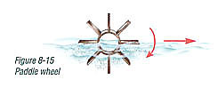
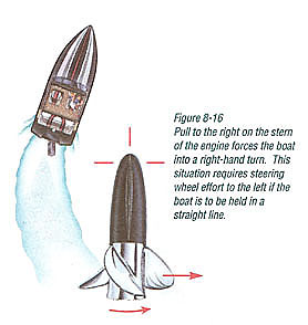
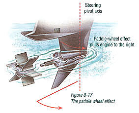
- As an outboard or stern drive is progressively raised, the propeller will eventually break the surface of the water. As this occurrence increases, a blade sweeping across the top, fanning through air, will not pull as hard in a sideways or propeller torque direction as the fully submerged blade sweeping across the bottom of the propeller arc. This will cause a right-hand rotation propeller to want to move or walk to the right much as a paddle wheel would try to do (Figure 8-15). This action in turn tries to pull the aft end of an outboard or stern drive to the right, thus causing the boat to want to go into a right-hand turn if not resisted at the steering wheel (Figure 8-16). This steering pull will either add to or subtract from the steering pull generated by the propeller shaft running trimmed in or trimmed out. When the propeller is elevated perhaps 5" or more above the standard height, the "paddle wheel" effect will completely dominate any other steering torque cause (Figure 8-17).
Centering the Engine
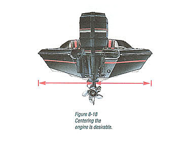
Generally, centering the engine within approximately 1/4" (6.4 mm) is desirable (Figure 8-18). As an engine (installed on a normal vee-bottom hull) is moved off center, it is increasingly lifted out of the water when the boat is turned in the opposite direction, thus increasing the likelihood of ventilation. Spray problems also may arise.
What is the "Trim Angle" of the Engine ?
Trim angle of an outboard or stern drive is the angle between the boat bottom and the propeller shaft formed by moving the engine/stem drive closer to the boat transom, called trimming "in" or "down" or "under," or moving the outboard/stem drive further away from the boat transom called trimming "out" or "up."
When a boat is cruising on plane and the trim is adjusted so that the propeller shaft is parallel to the surface of the water, that is said to be running at "neutral" or "zero" trim. On outboards without power trim, this angle is adjusted by changing the hole in which the adjustable tilt pin is inserted. The term "trim" is generally used when referring to adjusting the outboard or stern drive within the first 20° range of travel. This is the range used while operating your boat on plane. The term "tilt" is generally used when referring to adjusting the outboard or stern drive further up out of the water.
The trim angle of the outboard/stern drive has a distinct effect on the planing angle of the boat which, in turn, significantly alters top speed and handling. The engine/drive should be trimmed in for best start-up acceleration and shortest time to plane. The engine/drive would then be trimmed out for peak performance. If trimmed "in" (under) too far (Figure 8-19), the bow drops and the boat runs too wet. In this condition, top speed drops, fuel economy decreases, the boat may oversteer in one direction or the other ("bow steering"), and steering torque will increase (to the right with a right-hand rotation propeller). Occasionally, extreme trim under can cause a boat to list to the left (with a right-hand propeller).
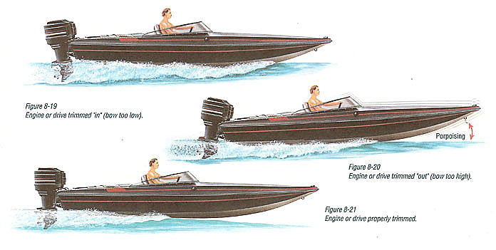
If trimmed "out" too far (Figure 8-20), the propeller may lose its hold on the water, fast vee-bottom boats may start to "walk" from right to left to right, etc. ("chine walking"), steering torque will increase in the opposite direction to that when trimmed in (Figure 8-19), and getting on plane may be difficult or labored. Porpoising of the boat may also occur.
Many newer outboards with power trim can only trim within the 20° range while underway above idle speed. All stern drives and older outboards with power trim have the capability of trimming all the way up, even when the boat is on plane.
However, it is unwise to operate on plane when trimmed beyond the maximum trim position (into the tilt range), as the engine no longer receives side support from the clamp brackets. Severe damage could occur in a turn if the gear housing should strike a submerged object. Figure 8-21 shows proper trim position.
How Does Trim Angle Affect Steering Torque?
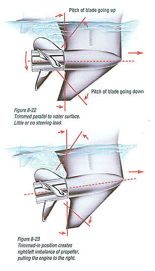
When the propeller is run fully submerged and with the propeller shaft approximately horizontal (parallel to the surface of the water) as shown in Figure 8-22, there should be little, if any, steering load. Although this also applies to stern drives, there are other complications due to a stern drive’s tilted steering axis, which can independently cause some steering torque.
However, with the engine or drive unit (right-hand rotation propeller) trimmed in (Figure 8-23), because of the propeller shaft tilt, the downward-moving blade on the right side of the propeller shaft has effectively more pitch, while the opposite is true of the upward-swinging blade on the left side (relative to the surface of the water). This right/left imbalance pulls the engine or drive unit to the right, and makes the boat want to go into a right-hand turn. Naturally, the driver must resist this force if the boat is to continue in a straight line.
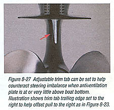
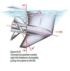
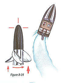
Figure 8-24 shows the gear housing and propeller of the trimmed-in engine as viewed from the surface of the water. Note that the propeller blade on the right side produces more thrust than the blade on the left, as indicated by different-size arrows, and that the boat is actually being pulled into a right turn.
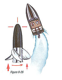
The entire situation reverses when the engine or drive unit is trimmed out well past horizontal (Figures 8-25 and 8-26).
To help counteract this steering imbalance, most outboards and all stern drives are equipped with an adjustable trim tab. Since the tab must be in one selected position, the driver must choose the engine trim position that he desires to balance (Figure 8-27).
In many boat and engine installations the engine or drive unit will be operated in a slightly trimmed-out position. This will cause the stern of the engine to move to the left, causing the boat to want to turn to the left. The trim tab, when properly adjusted, can steer the engine back in line, if, in this case, the trailing edge of the trim tab is moved to the left (Figure 8-27). For right-hand steering torque, the opposite is true.
What is Power Trim ?
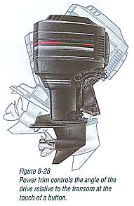
Trimming can be controlled far more conveniently by power trim, which is standard on most stern drives, standard on larger outboard motors, and optional on others.
Power trim permits control of the angle of the propeller shaft relative to the boat bottom at the touch of a button (Figure 8-28). While on plane, the angle of the boat bottom to the water has much to do with maximum top speed, fuel economy, handling, and choppy-water ride.
Boat bottoms have the least drag at an angle of from 3° to 5° with the water. If they run flatter than 3°, as most light planing boats tend to do, or steeper than 5°, as stern-heavy boats just barely on plane may do, efficiency suffers. Power trim can pay back dollars in fuel savings or give added thrills and safety with a faster, better-handling boat, or push a stern-heavy boat onto plane that otherwise might not make it.
Here’s a useful tip on operating power trim when a boat runs aground. It generally is best to not try to power out in forward. Rather, with the engine or drive trimmed out sufficiently (Figure 8-20) to not dig into the bottom, but still give the propeller a fair bite, operate carefully in reverse. This works better because, in the trimmed-out position in reverse, there is some downward thrust that helps lift the stern of the boat a little and forces propeller wash under the boat. Operating in forward tends to push the stern down harder against the bottom.
What is Power Steering?
Steering torque can be virtually eliminated with power steering. This does for your boat what power steering does for your car. It is available for both stern drives and larger outboards.
Power steering provides the ease and convenience of fingertip steering that's much easier to install than a hydraulic steering system. As long as the mechanical steering system remains in good working order, the system will provide effortless steering while eliminating feedback normally associated with mechanical systems.
Why Do I Need a Tachometer & Speedometer?
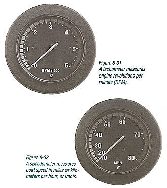
A tachometer ("tach") (Figure 8-31) measures engine RPM while the speedometer (Figure 8-32) measures boat speed in miles or kilometers per hour, or knots. A knot equals one nautical mile per hour, so it is incorrect to use the expression, "knots per hour." Here's the relationship between these three units of measurement:
- 1 Knot = 1.15 MPH = 1.852 KM/H.
- 1 MPH = 1.609 KM/H = 0.870 Knots.
An engine is designed to run at wide-open-throttle (WOT), within certain RPM limits. Without a tachometer, the operator has little opportunity to know if the engine is at a dangerously high or low RPM level. Once the correct propeller is selected, the engine will run at wide-open-throttle within the recommended maximum RPM range. Any deviation from this established WOT RPM other than that associated with climatic conditions, elevation, or gross load changes, is an indication of a performance problem.
A speedometer, when used with a tachometer, also will give hints of engine or boat problems, should an unusual speed drop occur. With experience, a boater will be able to detect problems at part throttle using the combination of the tach and speedometer. For a good, solid speed reading, it is important to install the speedometer pickup as low and close to the center of the boat as possible without creating a water disturbance ahead of the propeller or water intakes.
Tachometers and Speedometers as Performance Indicators
For engineering tests, extremely accurate and expensive tachometers are used. RPM information from these instruments provides unquestioned input for engineering evaluation.
Tachometers commonly installed in boats are not intended to provide this same degree of accuracy. Therefore, a slight variance from the true RPM is common with these instruments.
The common type of boat speedometer consists of a pitot (pronounced PEE-tow) tube, an instrument panel-mounted gauge which is calibrated to indicate miles per hour (MPH), kilometers per hour (KM/H), or knots, and the connecting tube or hose. The pitot tube is usually mounted on the transom so that the lower portion of the tube remains submerged in undisturbed water when the boat is underway. The forward portion of the pitot tube incorporates a hole, which points toward the direction of travel. Some newer outboard models have a pitot tube built into the leading edge of the gear housing strut.
As the boat moves forward, water enters the pitot tube through this hole and compresses the air trapped within the connecting hose and the bellows or Bourdon tube in the gauge. This water-to-air pressure, which varies in relation to the boat speed, actuates the needle movement mechanism, indicating the speed of the boat. The accuracy of the speedometer may suffer from winter freeze damage caused by trapped water in the line or instrument head, from a damaged pitot tube, from weeds, mud, or debris caught on the pitot tube, from a pitot tube that is partially or completely tilted up, or from an improper pi tot tube installation location.
For engineering tests, more accurate timing devices are used, such as computers and pressure transducers, whereby water pressure is converted into an electronic signal. This is sent to a computer which then calculates boat speed.
How Do Elevation and Climate Affect Performance?
Elevation has a very noticeable effect on the wide-open-throttle (WOT) power of an engine.
Since air (containing oxygen) gets thinner as elevation increases, the engine begins to starve for air, like using a supercharger in reverse. If the boat has been set up at a lower altitude and then moved to a much higher altitude, there will be a noticeable reduction in power, thus RPM.
Although some performance can be regained by dropping to a lower-pitch propeller, thus bringing the WOT RPM back into the recommended range, a basic problem still exists. The propeller is too large in diameter for the reduced power output.
The experienced marine dealer or a propeller repair station can determine how much diameter to remove from a lower-pitch propeller for specific high-elevation locations. In some cases, a gear ratio change to more reduction is possible and very beneficial. However, this fix is only safe while the power level is reduced. If the engine is again run at a lower altitude, the gear ratio change must be reversed to prevent excessive torque on drive train parts.
It is a fact that weather conditions exert a substantial effect on power output of internal combustion engines. Therefore, established horsepower ratings refer to the power that the engine will produce at its rated RPM under a specific combination of weather conditions now established by the International Standards Organization (ISO).
The marine engine rating code J1228 of the Society of Automotive Engineers (SAE) standardizes the computation of horsepower from data obtained on the dynamometer, correcting all values to the power that the engine will produce at 80.6°F (27°C) temperature, relative humidity of 60%, and a barometric pressure of 29.53 inches (750 mm) of mercury.
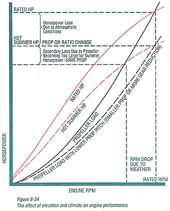
Summer conditions of high temperature, low barometric pressure, and high humidity all combine to reduce the engine power. This, in turn, is reflected in decreased boat speeds - as much as two or three miles per hour in some cases (Figure 8-34). Nothing will regain this speed for the boater, but the coming of cool, dry weather.
An engine, running on a hot, humid summer day, may encounter a loss of as much as 14% of the horsepower it would produce on a dry, brisk spring or fall day. The horsepower that any internal combustion engine produces depends upon the density of the air which it consumes and, in turn, this density is dependent upon the temperature of the air, its barometric pressure, and water vapor content (humidity).
Accompanying this weather-induced loss of power is a second, but more subtle, loss. At rigging time in early spring, the engine was equipped with a propeller that allowed the engine to turn within its recommended RPM range at full throttle. With the coming of the summer weather and the consequent drop in available horsepower, this propeller will, in effect, become too large. Consequently, the engine may operate at less than its recommended RPM.
Due to the horsepower/RPM characteristics of an engine, this will result in further loss of horsepower at the propeller with an additional decrease in boat speed. This secondary loss, however, can be somewhat regained by switching to a lower pitch propeller that allows the engine to again run at the recommended RPM.
For boaters to realize optimum engine performance under changing weather conditions, it is essential that the engine be propped to allow it to operate at or near the top end of the recommended maximum RPM range at wide-open-throttle with a normal boat load.
Not only does this allow the engine to develop full power, but equally important, the engine also will be operating in an RPM range that discourages damaging detonation. This, of course, enhances overall reliability and durability of the engine.
What are Trim Tabs and What Do They Do ?
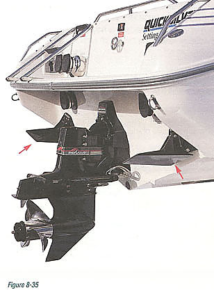
Trim tabs or after planes are a pair of flat, movable surfaces that extend aft from the boat bottom; one on each side of center. Each surface is individually adjustable up or down and, on the more sophisticated installations, by a remote control switch (Figure 8-35). These "trim tabs" are not to be confused with the small adjustable fin located on the gear housing just above and behind the propeller and used to help offset steering torque. It is also called a "trim tab".
After planes offer another method of trimming your boat in addition to power trim. When a boat's running attitude exceeds 5°, it is beginning to run increasingly less efficiently. Therefore, stern-heavy boats that need to run at a slow plane (20-25 MPH) will be greatly aided by after planes both in the efficiency and comfort departments.
Other benefits of after planes are faster planing, control of list or boat roll, and additional fuel savings made possible by allowing the boat to run at a lower engine RPM while remaining in an efficient planing attitude.
How Does Weight Distribution Affect Boat Performance ?
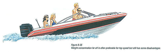
Weight distribution is extremely important; it affects a boat's running angle or attitude. For best top speed with a moderate to fast-planing boat, all movable weight-fuel, battery, anchor, passengers - should be as far aft as possible, to allow the bow to come up to a more efficient angle (3°-5°). But on the negative side of this approach is the problem that, as weight is moved aft, some boats will begin an unacceptable "porpoising" (bouncing). Secondly, as weight is moved aft, getting on plane becomes more difficult (Figure 8-36). Finally, the ride in choppy water with some boats becomes more uncomfortable as the weight goes aft. With these factors in mind, each boater should seek out what weight locations best suit his needs.
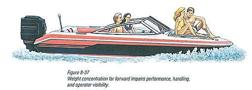
Weight and passenger loading placed well forward (Figure 8-37) increases the "wetted area" of the boat bottom and, in some cases, virtually destroys the good performance and handling characteristics of the boat. Operation in this configuration can produce an extremely wet ride, from wind-blown spray, and could even be unsafe in certain weather conditions or where bow steering may occur.
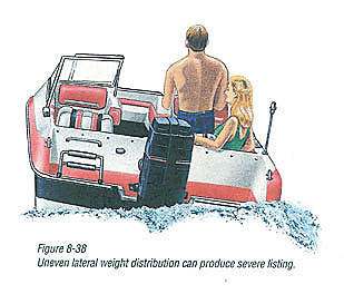
Weight distribution is not confined strictly to fore and aft locations, but also applies to lateral weight distribution (Figure 8-38). Uneven weight concentration to port or starboard of the longitudinal centerline can produce a severe listing attitude that can adversely affect the boat's performance, handling ability, and riding comfort. In extreme rough water conditions, the safety of the boat and passengers may be in jeopardy.
What is "Blowout" ?
Many high-performance boaters are aware of a phenomenon that limits their top speed below what would otherwise be possible with the available horsepower. This phenomenon is commonly called "gearcase blowout," "propeller blowout," or just "blowout."
Following is an explanation of why blowout occurs and how to correct it.
Why Blowout Occurs
To be practical, the torpedo of a non-racing gearcase or gear housing must be of a diameter and length just sufficient to house the shafts, gears, bearings, shift mechanism, exhaust passage, and a few other related parts.
Hydrodynamics designers can only hope to make the exterior shape of the gear housing the best they can (within their design constraints) to deter cavitation from occurring at the torpedo nose or any surface interruptions, such as a lubricant filler hole or water intake. Inevitably, as speed is increased, cavitation will occur.
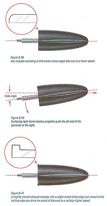
Since low pressure is the cause of cavitation, anything that further reduces the pressure on any side of the torpedo will hasten cavitation. Trimming the unit out will cause lower pressure on the underside of the torpedo, around the skeg; but an even more insidious culprit is the effect of a surfacing propeller pulling the aft end of the torpedo to the right with a right-hand rotation propeller. This causes lower pressure on the left side because of the angle at which the gearcase is forced to run through the water. This is commonly called the "crab" angle (Figure 8-40). The typical combination of a surfacing right-hand propeller and trimming out for best speed creates an extra-low pressure pocket on the lower left side of the torpedo.
However, cavitation itself does not cause the "blowout." Blowout occurs when the very low pressure cavitation bubbles eventually reach back to the aft end of the torpedo in sufficient quantity to suddenly pull in, or connect up with the engine exhaust gases. The cavitation and exhaust gas linkup is more prevalent with a non-through-hub exhaust propeller.
Once the connection is made, the exhaust follows the cavitation bubbles forward and floods out over the low-pressure side of the gearcase (the left side with a right-hand rotation propeller) and feeds back into the propeller blades, causing a sudden and drastic reduction of lift or thrust generated by the low-pressure side of the propeller blades. This partial unloading of the propeller creates four sudden reactions:
- The bow-lifting effect of the rake diminishes, causing the bow to drop.
- The hard-steering torque to the right is suddenly reduced, causing the boat to veer slightly to the left.
- The reduced load on the propeller allows the engine to rev up by 200 to 300 RPM.
- The wetter boat bottom and reduced propeller efficiency cause the boat to go slower by perhaps a couple of miles per hour.
How To Correct Blowout
With the latest gearcase designs, blowout should not be a problem below 80 MPH.
However, if the problem exists, contact your dealer. A special gearcase is available for many outboards and some stern drives that should cure the problem. The special gearcase has an extended torpedo nose, more rudder area, improved high-speed cooling water intakes, and a cupped skeg, which greatly reduces "crabbing" and steering pull to the right.
Other than running with excessive trim-out, the most significant cause of the blowout is a torpedo that has been buffed in a way that rolls off the trailing edge of the torpedo (Figure 8-39).
Some gearcases eliminate this problem by casting the torpedo in a slightly conical shape, leaving a slight raised sharp edge just ahead of the trailing edge of the torpedo (Figure 8-41). This patented feature, which can vary from .005" to .050" in height, retards the connection of exhaust to torpedo cavitation by creating a higher pressure fence much like the diffuser ring or flare on the aft end of a through-hub exhaust propeller, which deters the exhaust from being drawn forward into the low-pressure side of the propeller blades. Within the range given, the higher the bump, the higher the speed protection, but with slight additional drag.